Introduction
According to the ordered services, this document specifies the different types of power connections for the devices in our data centers.
There are two independent and completely separate power supply branches in both MasterDC data centers (Prague and Brno). Furthermore, each branch has its own high-voltage substation, a set of backup diesel generators, and battery UPS units.
Connecting a Device to the MasterDC PDU – Housing
Single Branch A/B Only
Shared housing spaces are powered by MasterDC PDUs, primarily intended from single-source wiring devices.
Connection Per Server:
- 1 x 230V IEC 60320 C13
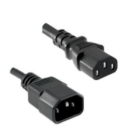
Dual A+B Connection
Shared housing areas are powered from redundantly wired MasterDC PDUs, where each PDU is supplied from a separate power branch. With the installation of a dual power supply, the technology must be equipped with two power sources.
Connection Per Server:
- 1 x 230V IEC60320 C13
- 1 x 230V IEC60320 C13
Device Connection in Rented Space – Rack Housing
The MasterDC secondary power distribution units supply the rented space in racks; the power supply is from both branches.
The size of the breaker rated current, and the final number of breakers depends on the ordered service and the expected performance of the installed device.
Single Branch A/B Only
An inlet from the secondary PDU from branch A/B is brought into the rented space.
Unless there is a previous agreement, the supply cables are terminated in a 1U power panel with 8 x CEE 7/5 sockets (CZ standard); the secondary MasterDC PDU is secured by circuit breaker C16A.
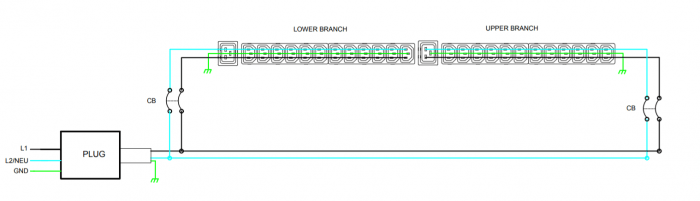
Customers PDU
![]()
If you are using your own PDU, the rated current and number of circuit breakers depends on the type and maximal supported rated current of the PDU. However, such wiring must always be arranged in advance with a MasterDC sales representative.
Dual A+B Connection
An inlet from the secondary PDU from branches A and B are brought into the rented space.
Unless there is a previous agreement, the supply cables are terminated in a 1U power panel with 8 x CEE 7/5 sockets (CZ standard); the secondary MasterDC PDU is secured by circuit breaker C16A.
For power redundancy, it is necessary to use a dual-source or ATS/STS device.
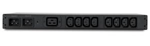
Customers PDU
![]()
If you are using your own PDU, the rated current and number of circuit breakers depends on the type and maximal supported rated current of the PDU. However, such wiring must always be arranged in advance with a MasterDC sales representative.
Furthermore, please be aware of the appropriate load distribution when redundantly connecting your device to individual PDUs from both power supply branches. When a power outage on one PDU occurs, the device’s performance will rely on the active PDU, which can be critical if the proper load distribution is not maintained.
This is especially true if the PDU has its own security of individual socket sections (bank 1, bank 2). In the case of mirror wiring to these individual sections of different PDUs, it must be ensured that the total required current on the section does not exceed the rated current of the section circuit breaker.
Use of ATS/STS for A+B
ATS/STS devices can be used to solve the situation of a redundant power supply from two independent power branches for single PSU devices.
This device provides automatic, fail-safe switching of the power supply from two independent power supply branches to the power outlets or the power terminal block.
A customised solution can be agreed upon with our sales representatives. Standardly it comes in 16 A and 32 A variants.